Project Goals
- Minimize cost
- Maximize ease of use
The goal of this project was to take the frame of a donor gas-powered motorcycle and convert it to an electric motorcycle (on a budget). Me and my classmate (and roommate) Duff Klaber, decided that we should make use of our apartment’s basement and see how cheaply we could build an electric motorcycle over the course of our final year at Cornell. The total cost target that we set for the entire electric motorcycle was $1000. This figure of course excludes the labor cost that would normally be associated with hiring a design engineer or machinist to design, build and assemble the product. We also wanted to consider ease of use: our goal was for anyone to be able to get on the bike and intuitively know how to ride it. When compared to the typical motorcycle controls (left hand clutch, right hand throttle and front brake, left foot shifter, right foot rear brake), electric motorcycles are very user friendly. They only require a throttle and two brakes, so anyone who has ridden a bicycle can pick up on it quickly.
Final Product
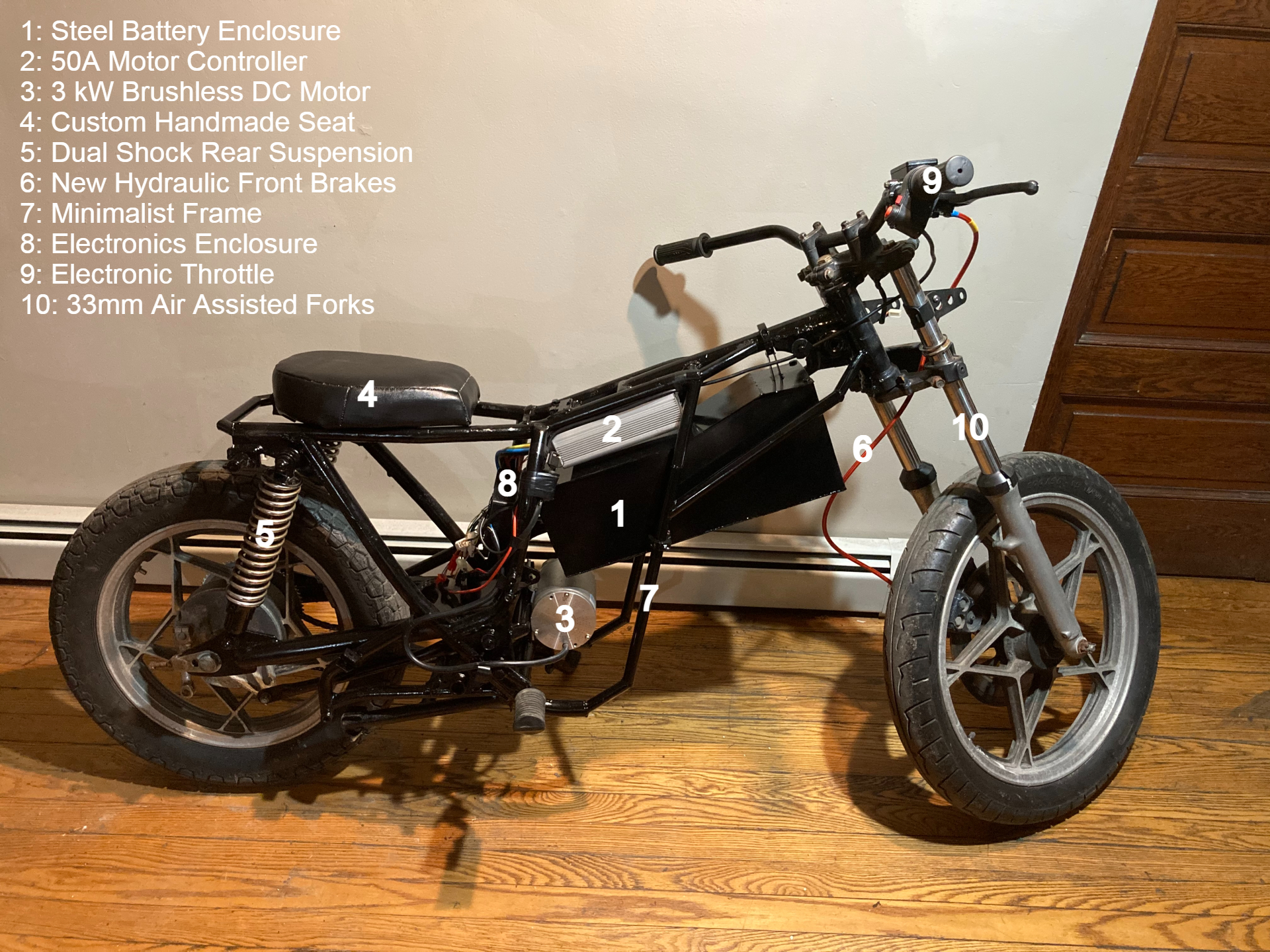
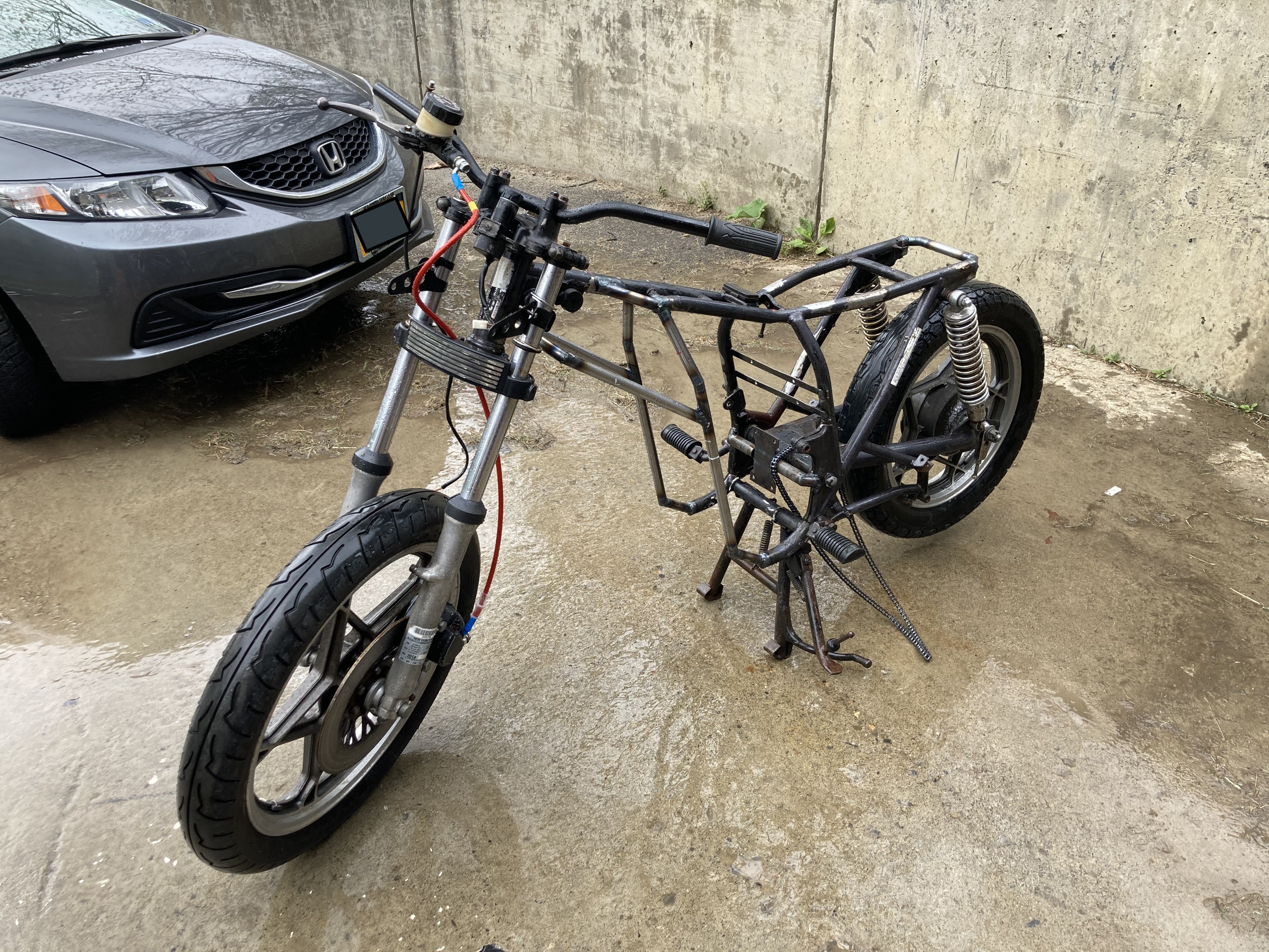
Our finalized electric motorcycle features a modified Suzuki GS450 with a cafe racer style frame, with a minimalist, modern design approach. It weighs approximately 185 pounds, sports dual shock rear suspension, and 33 mm air assisted forks for the front suspension. It is powered by a 3 kW brushless DC motor, and 6 12V 8Ah Absorbed Glass Mat batteries. The motor is controlled by a 24 Mosfet 50A Controller, and features forward and reverse functionalities in three different speeds. The motorcycle has newly installed hydraulic front brakes and has a 1.4 meter wheel base, and overall length of 2.07 meters. The entire project was completed using $928.53.
Donor Motorcycle
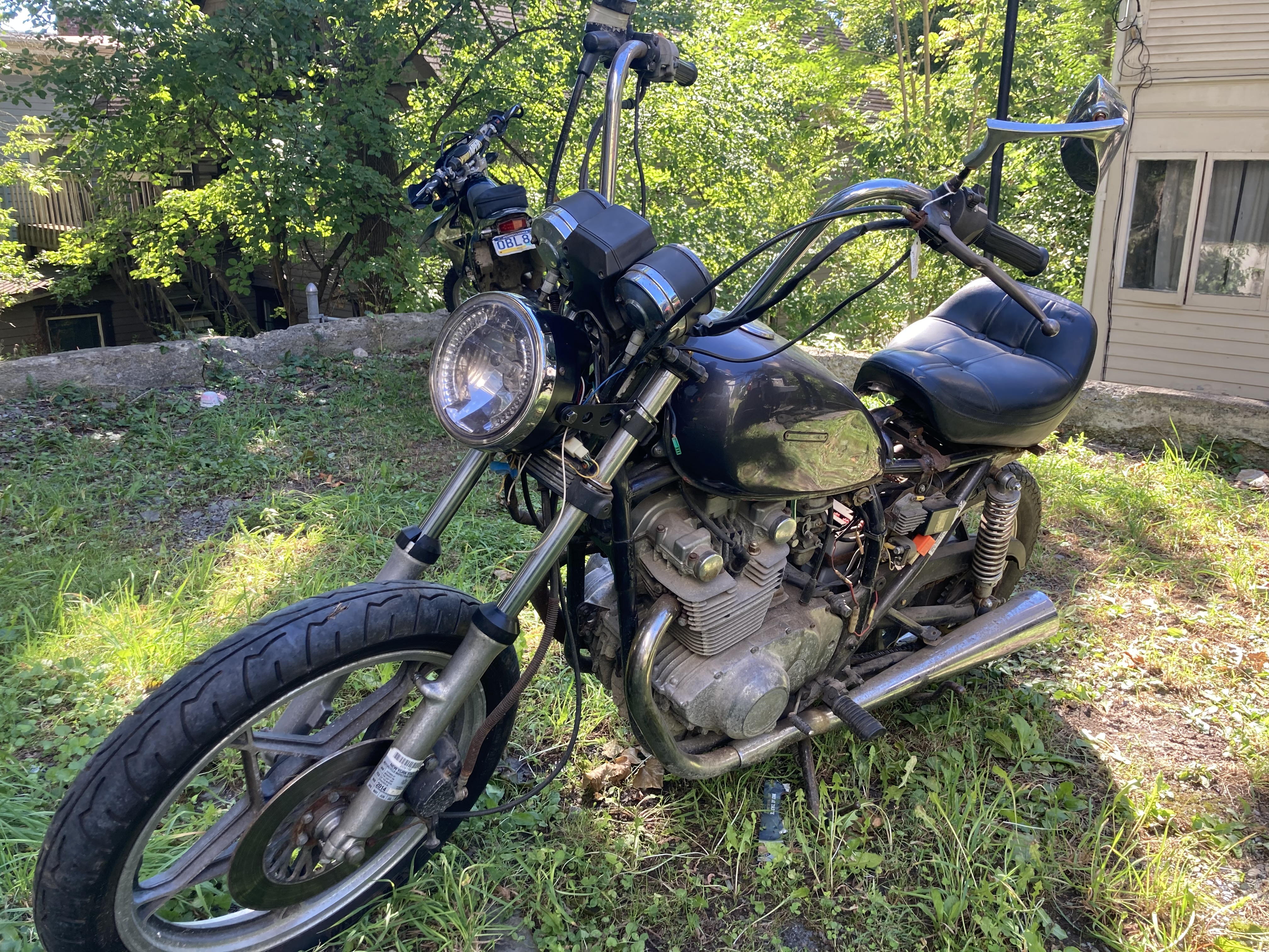
For our donor motorcycle, we purchased a 1980 Suzuki GS450 for $300, which had not run in many years but had functioning brakes and a fairly intact frame. The GS450 has a dry weight of 385 lbs, sports dual shock rear suspension, and 33 mm air assisted forks for the front suspension. Figure 2, below, shows the donor motorcycle in the condition we purchased it. The seat was not attached, and the high-handle bars and clunky exhaust did not fit the style we had envisioned for our electric motorcycle.
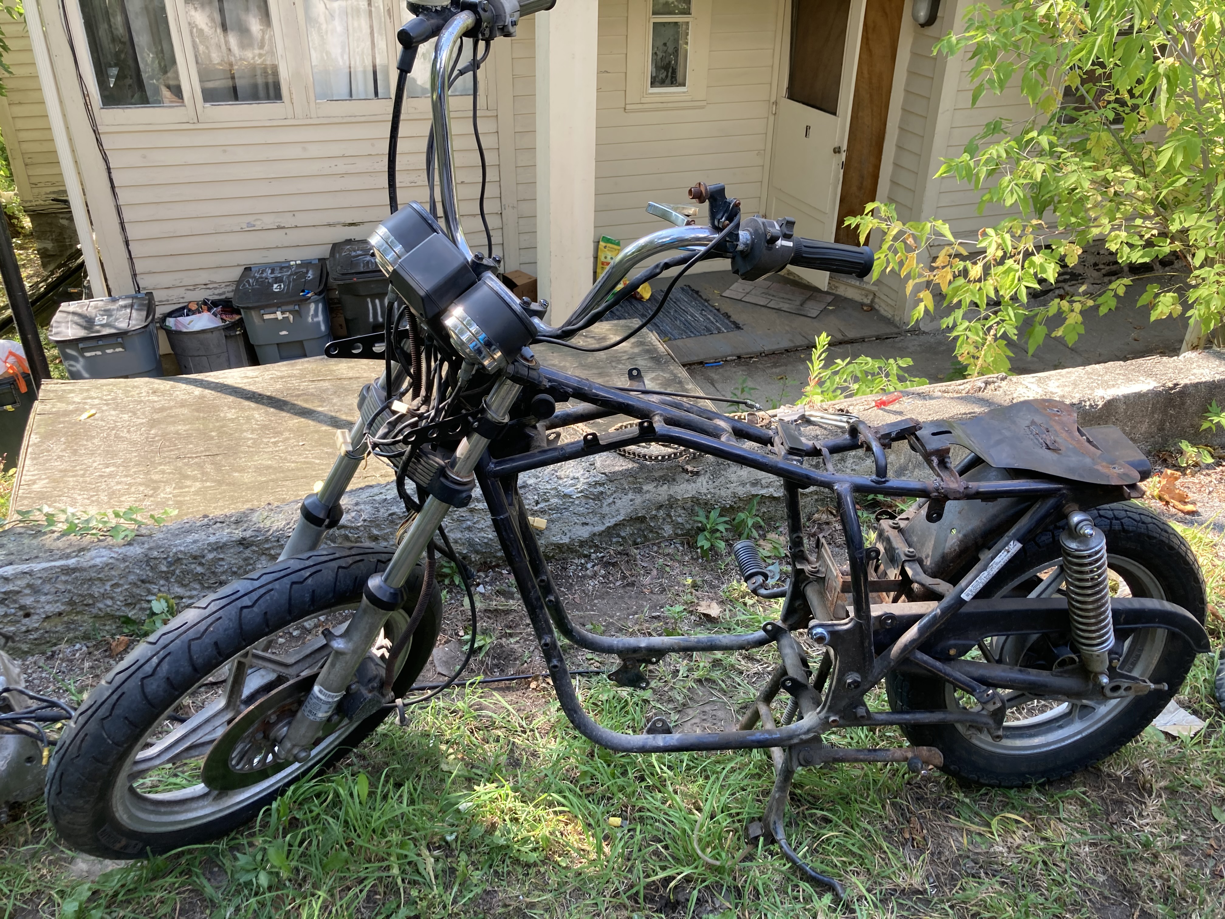
We began stripping the donor motorcycle, starting with removing any wiring related to the combustion engine, and removing the exhaust, fuel tank as well as engine. Stripping the motorcycle to its naked frame allowed us to quantify our dimensional constraints and give inspiration for possible frame design changes. Additionally, we removed the seat mounting plate which had been roughly welded on by the previous owner.
Motor
In selecting the right motor, the first broad choice we had to make was whether we wanted to use a brushed or a brushless DC motor. Brushed motors use a pair of carbon brushes to transfer DC power to the commutator of the armature, which creates an electromagnetic field, repelling the permanent magnets surrounding the wound armature. This causes the armature to rotate, and as it rotates, the polarities of the rotor windings are constantly being reversed such that the armature continues to be repelled in such a way that it can continue rotating. The commutation of the windings is done mechanically, meaning that brushed DC motors are much simpler and are thus cheaper. However, since the brushes and commutator are in constant physical contact with the shaft, more energy is lost to heat, and the lifespan of a BDC motor is reduced, and potential for motor maintenance is introduced. Brushless DC motors on the other hand do not have brushes and a mechanical commutator but instead use a controller to rotate the shaft. This means that in general, brushless motors tend to be more expensive, but are smaller and more efficient.
Since the frame without the massive combustion engine and fuel tank leaves ample space, the size benefit associated with a brushless motor did not really factor into our motor selection decision. Additionally, both motors are capable of speed control and regenerative braking, although a brushless motor is likely to be more precise considering the sensors and controller associated with it are more complex. Our main criterion then was the efficiency of the motor, as well as ease of controller compatibility. Since we had originally planned to program the controller ourselves, we ultimately decided to select a brushless DC motor. We also found that for the power range requirements we were considering, going with a brushed motor did not make a significant enough monetary difference for it to be worth the potential headache in designing a controller for it.
The next consideration we had to consider for our motor was what performance we desired. Ultimately we wanted to design a motorcycle that would be to accelerate fairly well up a steep hill, and reach top speeds comparable to a scooter. Our desired performance prioritized peak torque and power over endurance and ride time.
The motor that we selected for our electric motorcycle is a 72V 3kW brushless DC motor. The motor is rated for 45A, and has a maximum RPM of 5800. The motor has an aluminum body and comes with a pre-welded mounting plate.
The final factor in our motor selection decision was simply the part lead time. We had found more powerful 5kW or even 8kW motors that exceeded our performance requirements, and would have resulted in a more powerful overall motorcycle, but all of these possible motors had lead times of between 1-2 months, and the timeline for our motorcycle build that we had in mind did not allow for such a large lead-time. In retrospect, if we had done the motor selection sooner, we would have been able to take this lead-time into account, and could have obtained a more powerful motor. However, these more powerful motors would have also been significantly more expensive.
Motor Mount
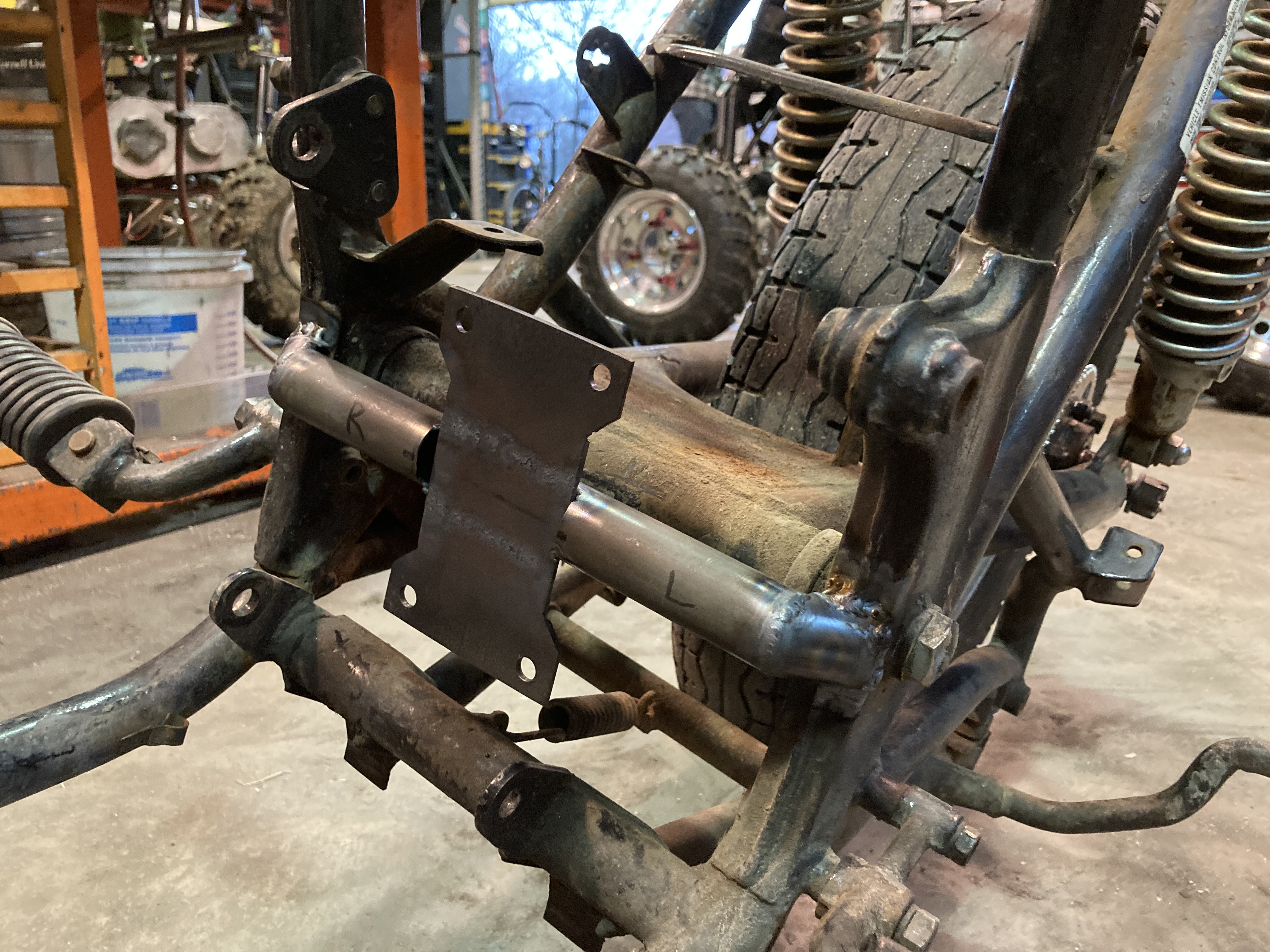
Since the 3 kW motor that we purchased arrived with a pre-welded mounting plate, we designed our motor mount to use the same bolt pattern. We wanted to make the aesthetic of the mounting system match the lower frame of the motorcycle so that it would be difficult to discern that any modifications had been made. Thus we used 1 inch outer diameter tubing and welded this to a .09 inch thick sheet metal plate. The mounting plate has to withstand significant torque loading from the motor, so we performed finite element analysis before fabricating the part and welding it to the frame. The mounting plate was recessed into the tube in order to increase weld area and provide a larger lever arm to withstand torque. The weld bead was modeled with a fillet in CAD.
The analysis was set up to simulate the most extreme load case: the full torque of the motor (7Nm) being applied while the rear wheel remains stationary (Figure 4). Ideally this scenario would never occur during operation, as our calculations show us the motor has ample torque to climb steep hills without stalling. However, we wanted to ensure no damage would occur to the motor mount if it did. Fixed supports were applied to both ends of the tube that will be welded to the frame and a remote force was applied at the top of the motor sprocket (where the chain would be in tension resisting movement). This remote force is transmitted through the two mounting feet of the motor.
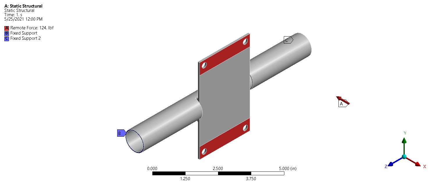
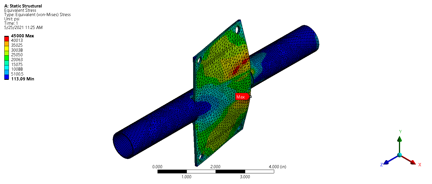
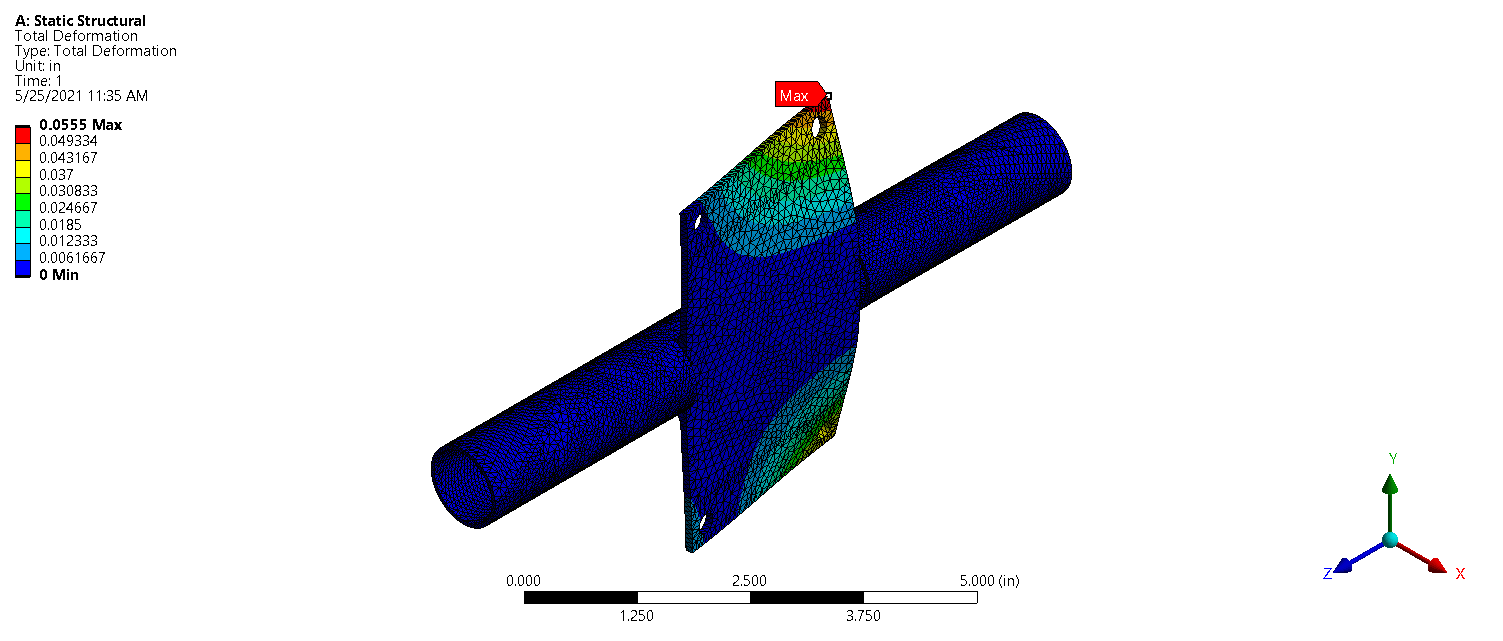
Results seen in Figure 5 suggest that the maximum stress seen by the motor mount is around 45ksi, but the point of maximum stress is on a corner and may be artificially high. Additional probes in the areas of highest stress showed that the maximum realistic stress may actually be closer to 41ksi. Considering the yield strength of our steel is 53.7ksi, the motor mount has a factor of safety of 1.31. Results shown in Figure 6 show a maximum deformation of .055in, which we deemed an acceptable margin. Performing this analysis gave us confidence to proceed with our design.
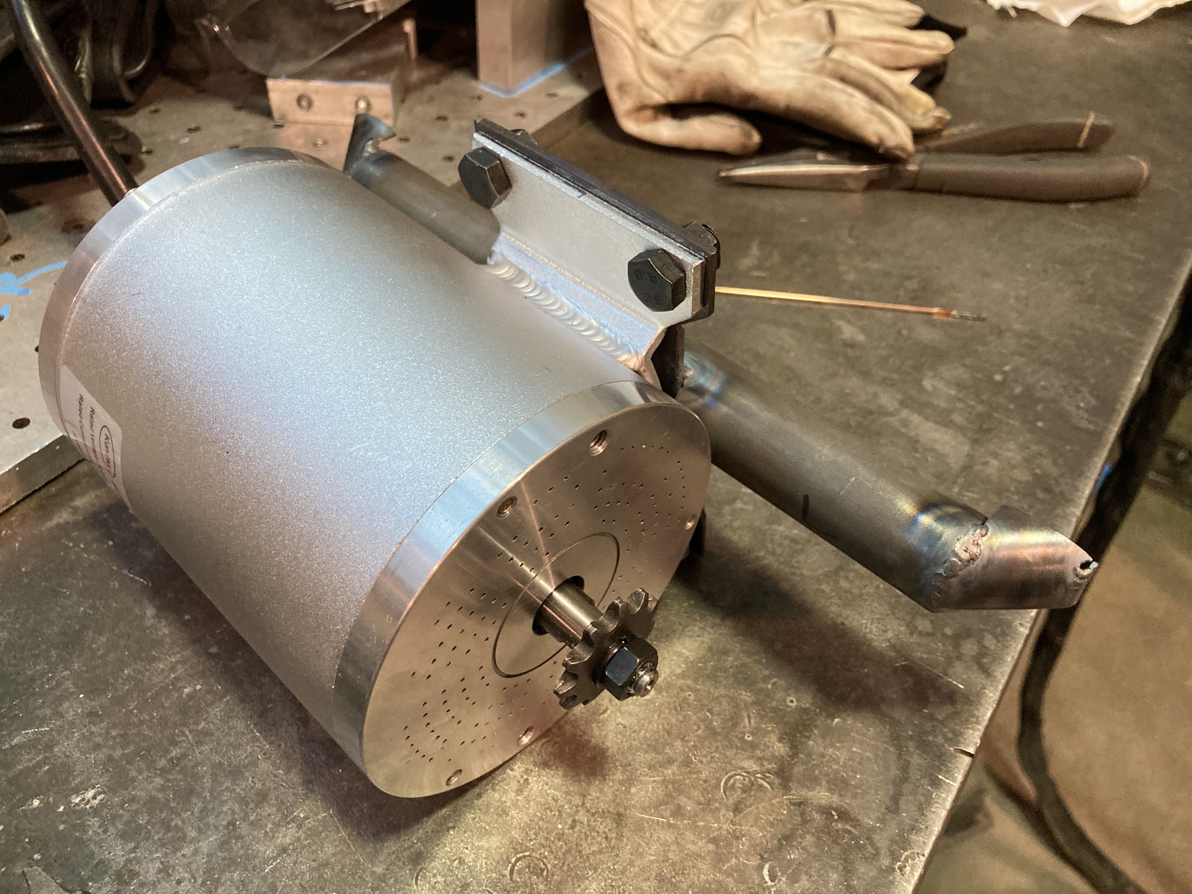
Once we verified that the mounting system would be sufficiently stiff to withstand the load from the motor, we fabricated the motor mounting system, making sure the motor fit correctly (Figure 7), and then welded the custom motor mount to the motorcycle frame (Figure 8).
Controller
The controller we used for this project was purchased directly with the motor and was thus pre-programmed. This controller is 209 mm x 117 mm x 60 mm (L x W x H) and supports up to 50 Amps, and has voltage and power specifications compatible with our motor. It has forward and reverse functions and three speed settings. The wires are managed through a singular wire grommet and are color coded. The controller also sports lateral flanges to help with mounting, which we had to widen slightly for the bolts we used.
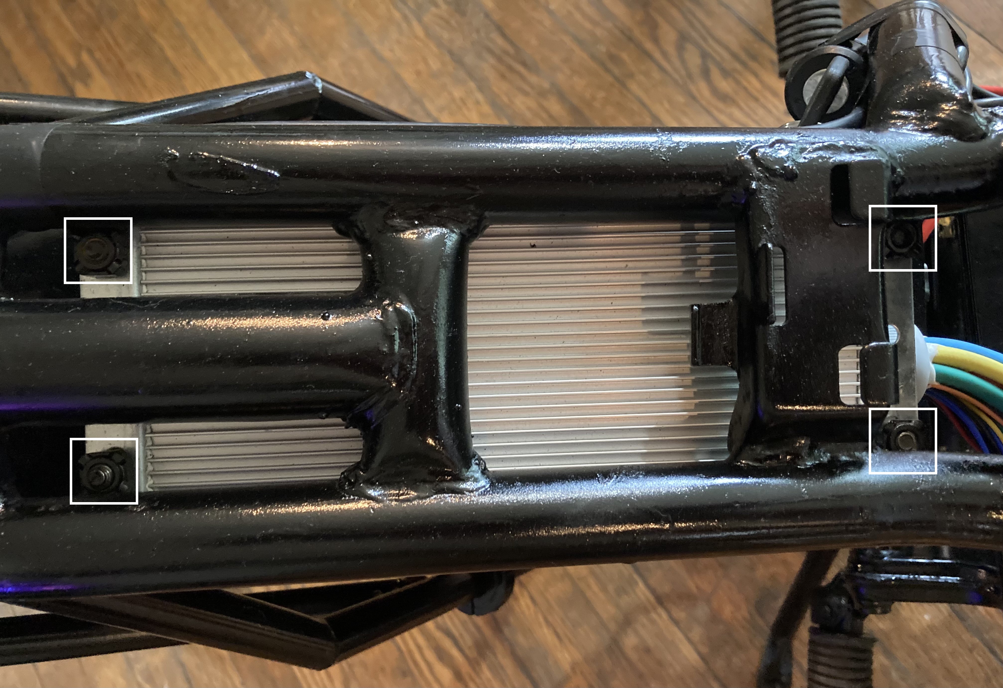
To mount the controller to the frame of the electric motorcycle, we used 4 square weld-nuts welded underneath the central frame tube. This allows the controller to be easily be removed in case any re-wiring needs to be done, and also allows the controller and the subsequent wiring to be conveniently located in relation to the motor and the electronics enclosure. The controller can be seen on the frame in Figure 9, with the 4 weld-nuts boxed in white.
Batteries and Enclosure
For the batteries, our main criteria were price, resistance to vibration and motor compatibility. The broad choices of batteries available for our purposes were either lead-acid batteries or lithium ion batteries. Lithium ion batteries have specifications that are almost always superior to lead-acid batteries. They are much lighter, have a higher energy density, and usually last longer than lead-acid batteries. Understandably, this makes lithium ion batteries significantly more expensive than lead-acid batteries. Since we did not design the bike for longevity, and the weight of the bike had been significantly reduced by removing the combustion engine and fuel tank, we felt that we could afford the extra weight incurred by using lead-acid batteries. Additionally, since space in our frame was also not an issue, the much higher energy density of lithium ion batteries would not have been necessary.
Within the category of lead-acid batteries there is also room for selection. Flooded lead acid batteries are reliable and are one of the cheapest batteries on the market. However, we desired batteries that would be shock and vibration resistant due to the nature of their application. For this reason, we chose Absorbed Glass Mat (AGM) batteries. In AGM batteries, the sulfuric acid is absorbed by a fiberglass mat rather than being flooded. This makes AGM batteries incapable of spilling, and means they can be stored in any orientation. This was also an important criteria for us when selecting a battery because we had considered storing our batteries vertically rather than horizontally, and wanted to have that option available to us. AGM’s also do not require maintenance and charge up to five times faster than flooded batteries [1].
Our final battery selection was 6 12V 8Ah. Each battery is 5.94 inches x 2.56 inches x 3.94 inches, weighing 4.96 lbs. Thus the total weight of the batteries is just under 30 pounds, at 29.76 lbs.
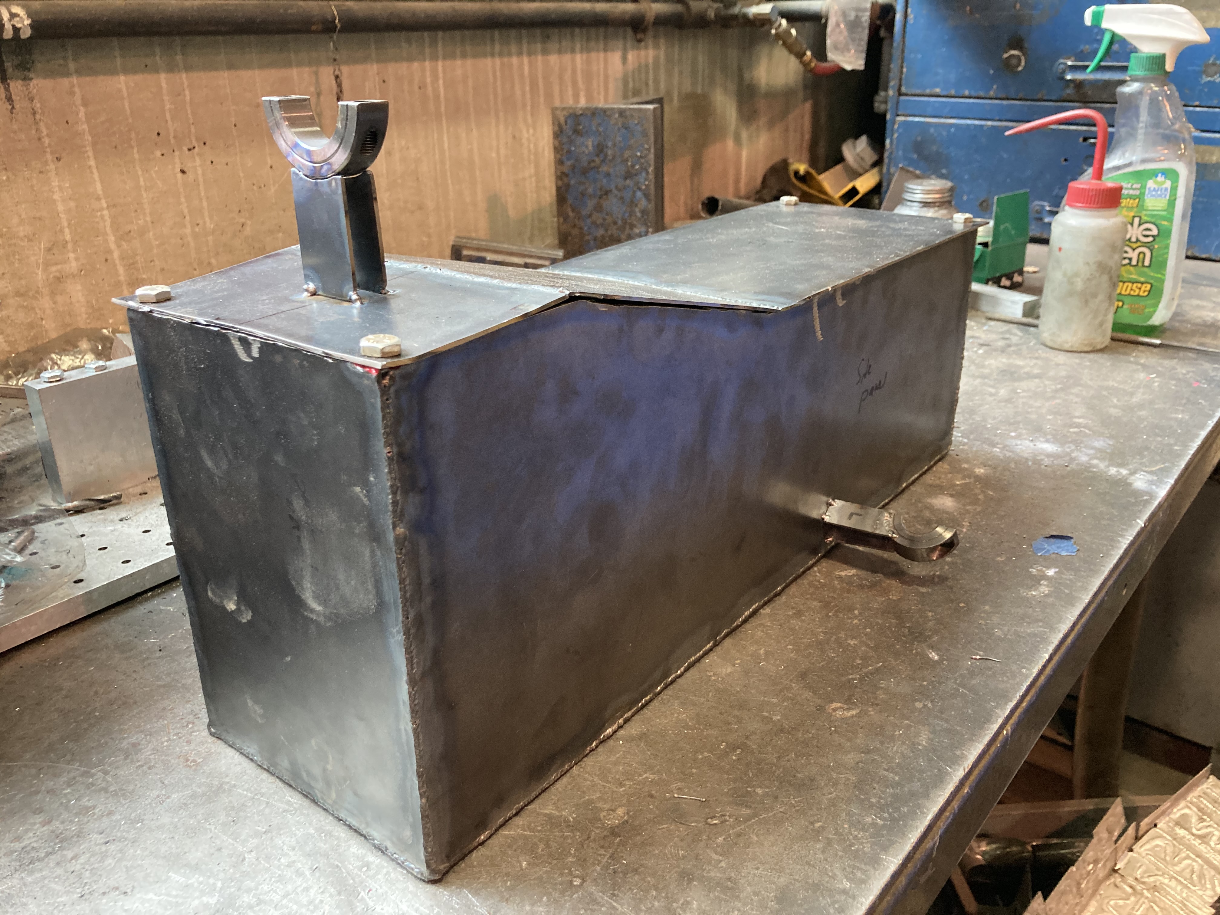
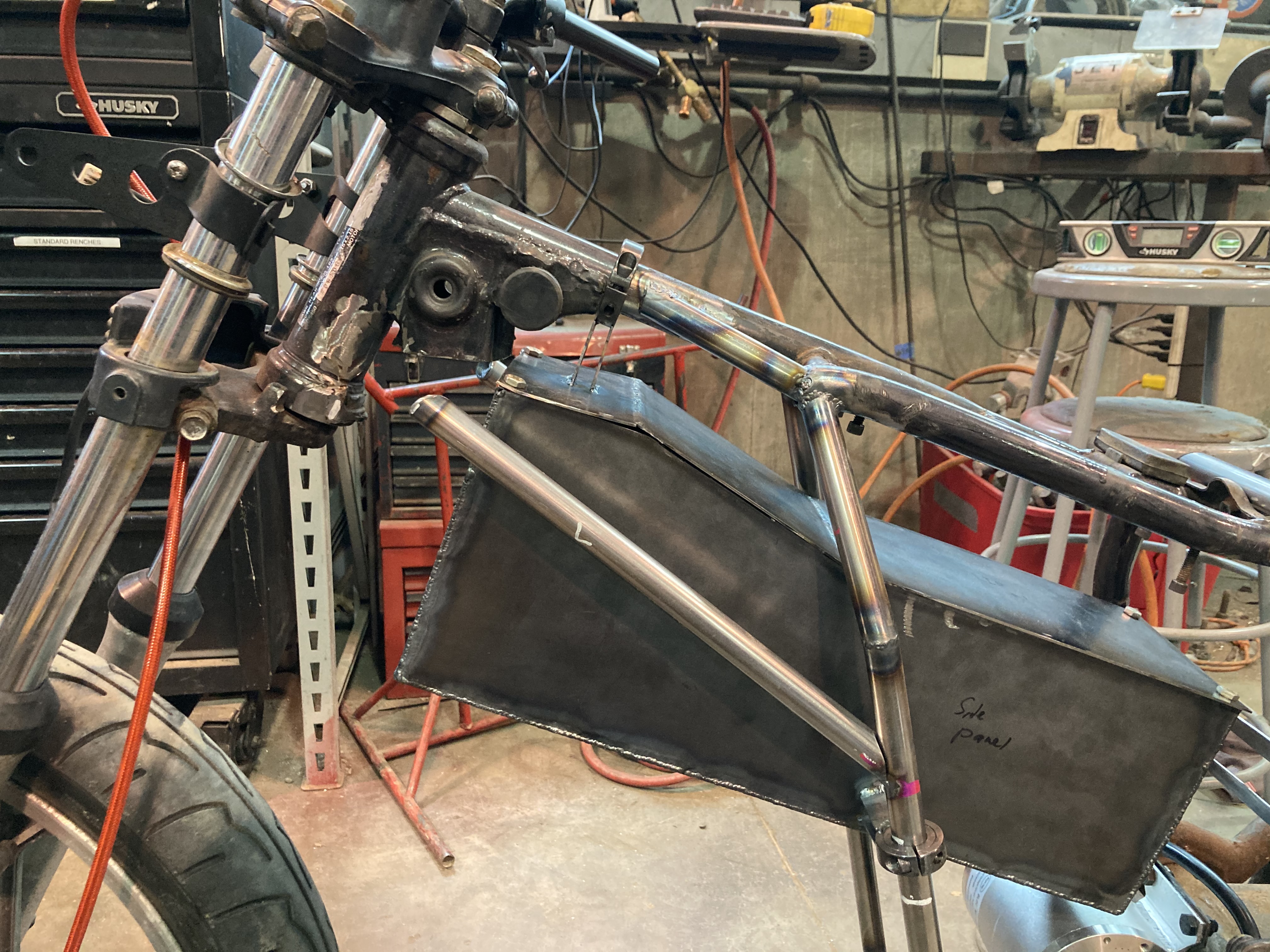
To house the batteries, we designed an enclosure that would be able to be removed without specialized tools or very much effort to allow for easy charging after the batteries had been depleted. To do this, the battery enclosure is fixed to the tubular frame using two-piece shaft collars. One larger steel shaft collar, seen on the top of the enclosure lid in Figure 10 and two lateral steel shaft collars keep the enclosure centered and support the weight of the batteries.
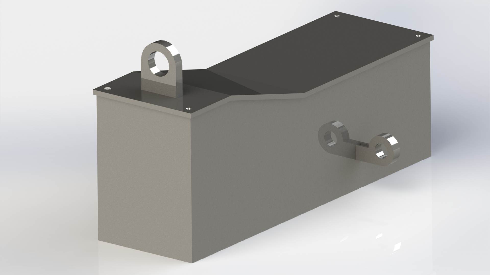
We designed the battery enclosure to consist of sheet metal parts that would be able to be welded together. We used 16 gauge low-carbon steel for the entire battery enclosure. We first cut out all of the sheet metal components using an angle grinder and a foot shear, spot welded the walls of the enclosure in place, making slight adjustments and finalized the welds. We carefully measured the required lengths for the shaft collar struts extruding from the sides of the enclosure so that they would be able to line up with the frame. The entire battery enclosure is 7.44 inches in height, 18.57 inches long, and 5.57 inches wide, allowing the batteries to fit snugly within the enclosure. To ensure minimal jostling of the batteries, we also incorporated lateral foam strips within the battery enclosure. The empty enclosure and lid weighs approximately 10.2 pounds, meaning the entire enclosure and battery array weighs about 39.96 pounds. Below, in Figure 11 is the finished battery enclosure, with the top half of the shaft collars completely separated.
To demonstrate the functionality of the shaft collars, see Figure 12, below.
Frame
Very early on in the design process, it became clear the existing frame would be excessively large for the components we planned to install. Even with our motor, controller, and relatively large lead acid battery pack, the frame would have been mostly empty. In addition to improving the appearance of the vehicle, we decided to modify the frame in order to decrease weight and increase rigidity.
There are three basic types of motorcycle frame: backbone, cradle, and perimeter. The backbone frame is the cheapest and simplest option, using one large, mostly horizontal tube/beam to connect the steering tube back to the seat and then a vertical section to mount the engine. In this design, the engine hangs on the bottom of the frame. The cradle frame has one or two bars going down from the steering tube to support the engine. In this configuration the engine is within the frame and can be mounted in many spots. Finally, the perimeter frame connects the steering tube as directly as possible to the rear swingarm mount point for minimal weight and maximum rigidity. The engine sits higher in the frame in this configuration, as the members go around its perimeter. This is commonly done with small tubes in triangulated arrangements (trellis frame).
We iterated through a few frame designs getting inspiration from these three basic motorcycle frame types, which can be seen in detail in the report.
Our stock Suzuki utilized a double cradle design that had two members going under the engine to support it. We wanted to eliminate these two bars in order to give the bike a sleeker, taller look as well as getting rid of the image of an “empty” frame. This essentially left us with a backbone frame, but because it was not designed as a backbone frame we anticipated the top tube wasn’t strong enough to keep the frame rigid. We took cues from the perimeter frame, except instead of the engine we routed the new tubes around the battery pack (our motor is small enough that no major packaging issues were encountered for that component). We also ran bars to enclose the motor, both for aesthetic reasons and protection. This design lightened our frame, allowed us to create good mounting points for the battery pack, and maintained rigidity. It also dramatically changed the look of the vehicle so it appears smaller, lighter, and more manageable.
Reflection
Now that the prototype vehicle is fully assembled and functional, we can reflect on some of the design choices that we made. The most obvious oversight that we discovered during the first drive was the chain selection. Our motor came with 8mm roller chain sprockets, so we continued to use this size. However, the nature of motorcycle swing arms is such that the distance between the front and rear sprockets changes slightly. With larger chain typical of full size motorcycles, this change in tension is perfectly acceptable without the chain skipping any teeth or falling off the sprockets. However, the relatively long length of our chain coupled with the small size makes it prone to falling off the sprockets under sudden acceleration or braking. Over-tightening the chain may result in it snapping, so we also want to avoid that. Our chain selection was somewhat constrained because the only sprockets available with the proper mounting holes for our engine are for smaller chain sizes. We did not take this fully into account when selecting our motor. Given more time, our preferred solution would be to manufacture a custom front sprocket for a larger chain size. Given the time left in the semester and the resources available, we will be installing a chain tensioner/guide to keep the chain on the sprockets.
We were generally pleased with our frame modifications and packaging. We decreased the weight of the vehicle by over 190lbs while maintaining frame rigidity and mounting all necessary components in a secure and appealing manner. One fundamental way we would change our approach is choosing a donor vehicle closer to our desired end product. We were slightly constrained during our selection process because we needed the bike quickly and had a low price cap, but choosing a lighter, smaller motorcycle instead of a large cruiser like the GS450 would have resulted in less frame work and a lighter and nimbler motorcycle. Additionally, given more time, it would have been interesting to design the controller from scratch so that we could have made finer adjustments to the desired motor modalities.