Overview
As a fun side project, and to get more acquainted with the 3D printers in our laboratory, I decided to design and 3D print a Reuleaux mechanism with the constraint that it should be small enough to fit on my desk. This translated to a roughly 6 inch cubed constraint. Cornell University has a vast collection of Reuleaux mechanisms in the Kinematic Models for Design Digital Library (KMODDL) which includes open access, multimedia resources for learning and teaching about kinematics – the geometry of pure motion – and the history and theory of machines. These mechanisms and machines are housed in Cornell University’s Sibley School of Mechanical and Aerospace Engineering in Duffield and Upson hall.
The particular mechanism I chose, is the D08 Double-Slider Crank mechanism which features 2 revolute joints and 2 sliding joint, converting between rotational and linear motion. Since the end effector is constrained to the linear channel, there is only one degree of freedom which either specifies the position along the channel or the orientation of the crank using an angle. The horizontal slider forces the constrained vertical slider up and down cyclically. There are many instances of the slider crank that can be found in the real world, but perhaps the most famous use of this mechanism is the piston. Here, linear motion in the channel caused by combustion is converted to rotational motion. Another example could be a conversion from rotational motion into linear motion to perform a crushing mechanism. This particular mechanism isn’t necessarily very practical, but was fun to make.
CAD
All of the mechanism’s parts were printed on our lab’s flashforge 3D printer, besides the small bearing which connects the horizontal sliding piece to the crank arm. Below is the imbedded CAD assembly using eDrawings - drag and scroll to move the assembly.
Implementation
Hardware:
- 4 x AS 1420 M4 screw
- 1 x 1/8” ID bearing
Kinematics
The kinematics of this mechanism are very straightforward, but I thought I’d quickly derive the input/output relationship here anyway. First we define the input and output:
Input: Handle
Output: Vertical slider
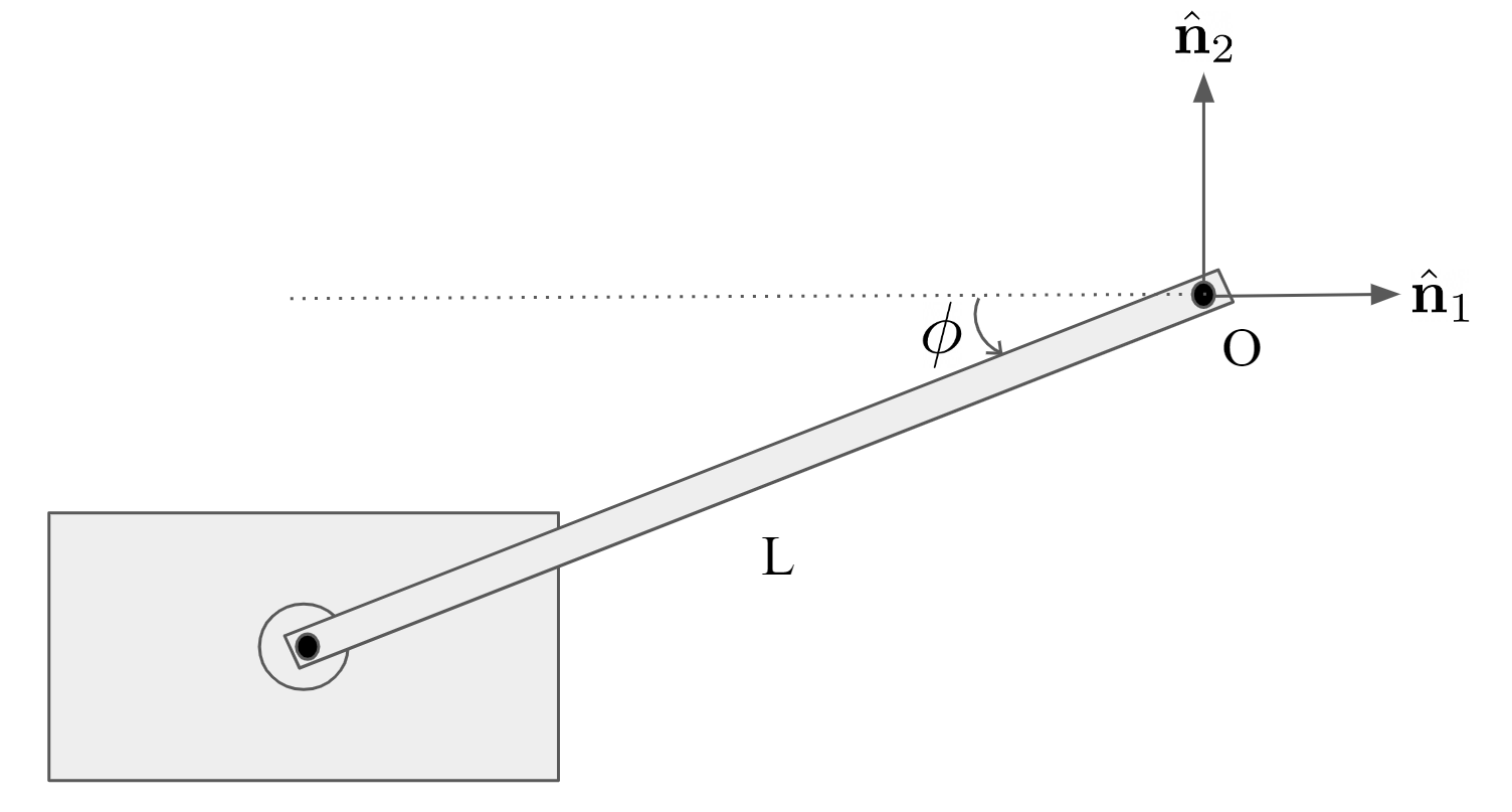
We can describe the motion of the horizontal sliding block in the inertial frame depicted above as:
\[\begin{equation} ^N\textbf{r}_O = -Lcos(\phi)\hat{\textbf{n}}_1 - Lsin(\phi)\hat{\textbf{n}}_2 \end{equation}\] \[\begin{equation} ^N\dot{\textbf{r}}_O = L\dot{\phi}sin(\phi)\hat{\textbf{n}}_1 - L\dot{\phi}cos(\phi)\hat{\textbf{n}}_2 \end{equation}\]Since the vertical piece is coupled with the motion of the horizontal piece, its movement in the plane can simply be modeled as the vertical component of the horizontal sliding piece. Therefore, the input-output relationship is simply:
\[\begin{equation} \boxed{\frac{Input}{Output} = \frac{\dot{\phi}}{-L\dot{\phi}cos(\phi)}} \end{equation}\]